What Is Ladder Diagram Control . ladder logic (also known as ladder diagram or ld) is a programming language used to program a plc (programmable logic controller). a plc ladder diagram is a graphical representation of the logical control functions performed by a programmable logic controller. They are called “ladder” diagrams. what is ladder logic & ladder diagram? Ladder logic is one of the top 5 most popular types of plc programming languages. ladder logic tutorial with ladder logic symbols & diagrams. Over time they have advanced to become more user friendly, efficient, smaller and less expensive. Two vertical control rails and horizontal logic. a ladder diagram is a type of schematic diagram used in industrial automation, describing circuits for logic control. Plcs have exploded in the controls market and are used throughout the world. ladder diagrams are specialized schematics commonly used to document industrial control logic systems.
from dxosuqmol.blob.core.windows.net
They are called “ladder” diagrams. Ladder logic is one of the top 5 most popular types of plc programming languages. what is ladder logic & ladder diagram? a plc ladder diagram is a graphical representation of the logical control functions performed by a programmable logic controller. a ladder diagram is a type of schematic diagram used in industrial automation, describing circuits for logic control. ladder logic tutorial with ladder logic symbols & diagrams. Two vertical control rails and horizontal logic. Plcs have exploded in the controls market and are used throughout the world. Over time they have advanced to become more user friendly, efficient, smaller and less expensive. ladder diagrams are specialized schematics commonly used to document industrial control logic systems.
What Is Ladder Logic Diagram Explain at Antonia Baldwin blog
What Is Ladder Diagram Control a ladder diagram is a type of schematic diagram used in industrial automation, describing circuits for logic control. They are called “ladder” diagrams. Ladder logic is one of the top 5 most popular types of plc programming languages. what is ladder logic & ladder diagram? Two vertical control rails and horizontal logic. a ladder diagram is a type of schematic diagram used in industrial automation, describing circuits for logic control. ladder diagrams are specialized schematics commonly used to document industrial control logic systems. Plcs have exploded in the controls market and are used throughout the world. a plc ladder diagram is a graphical representation of the logical control functions performed by a programmable logic controller. ladder logic (also known as ladder diagram or ld) is a programming language used to program a plc (programmable logic controller). Over time they have advanced to become more user friendly, efficient, smaller and less expensive. ladder logic tutorial with ladder logic symbols & diagrams.
From www.researchgate.net
An example of ladder diagram Download Scientific Diagram What Is Ladder Diagram Control ladder diagrams are specialized schematics commonly used to document industrial control logic systems. Two vertical control rails and horizontal logic. Over time they have advanced to become more user friendly, efficient, smaller and less expensive. a plc ladder diagram is a graphical representation of the logical control functions performed by a programmable logic controller. what is ladder. What Is Ladder Diagram Control.
From learn.automationcommunity.com
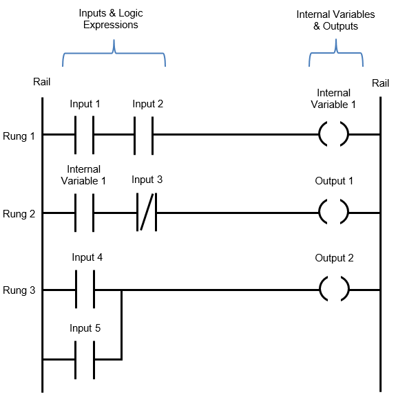
A Simple Ladder Diagram with NO and NC Contacts What Is Ladder Diagram Control ladder logic tutorial with ladder logic symbols & diagrams. Plcs have exploded in the controls market and are used throughout the world. Two vertical control rails and horizontal logic. a ladder diagram is a type of schematic diagram used in industrial automation, describing circuits for logic control. a plc ladder diagram is a graphical representation of the. What Is Ladder Diagram Control.
From control.com
Ladder Diagram (LD) Programming Basics of Programmable Logic Controllers (PLCs) Automation What Is Ladder Diagram Control Over time they have advanced to become more user friendly, efficient, smaller and less expensive. ladder logic tutorial with ladder logic symbols & diagrams. a ladder diagram is a type of schematic diagram used in industrial automation, describing circuits for logic control. Ladder logic is one of the top 5 most popular types of plc programming languages. . What Is Ladder Diagram Control.
From circuitplanteartc.z14.web.core.windows.net
Ladder Diagram Of The Control Circuit What Is Ladder Diagram Control Plcs have exploded in the controls market and are used throughout the world. Ladder logic is one of the top 5 most popular types of plc programming languages. a ladder diagram is a type of schematic diagram used in industrial automation, describing circuits for logic control. what is ladder logic & ladder diagram? a plc ladder diagram. What Is Ladder Diagram Control.
From stewart-switch.com
Plc Ladder Diagram For Elevator Control What Is Ladder Diagram Control what is ladder logic & ladder diagram? Two vertical control rails and horizontal logic. a ladder diagram is a type of schematic diagram used in industrial automation, describing circuits for logic control. ladder diagrams are specialized schematics commonly used to document industrial control logic systems. Plcs have exploded in the controls market and are used throughout the. What Is Ladder Diagram Control.
From electricalacademia.com
Ladder Diagram Schematic Diagram Wiring Diagram Electrical Academia What Is Ladder Diagram Control ladder diagrams are specialized schematics commonly used to document industrial control logic systems. ladder logic tutorial with ladder logic symbols & diagrams. Over time they have advanced to become more user friendly, efficient, smaller and less expensive. ladder logic (also known as ladder diagram or ld) is a programming language used to program a plc (programmable logic. What Is Ladder Diagram Control.
From stock.adobe.com
PLC Ladder Diagram Tank Liquid Level Control System Векторный объект Stock Adobe Stock What Is Ladder Diagram Control ladder logic tutorial with ladder logic symbols & diagrams. Over time they have advanced to become more user friendly, efficient, smaller and less expensive. a plc ladder diagram is a graphical representation of the logical control functions performed by a programmable logic controller. They are called “ladder” diagrams. a ladder diagram is a type of schematic diagram. What Is Ladder Diagram Control.
From schematicfixcinnamon.z5.web.core.windows.net
Logic Gates In Plc Ladder Diagram Pdf What Is Ladder Diagram Control They are called “ladder” diagrams. a ladder diagram is a type of schematic diagram used in industrial automation, describing circuits for logic control. ladder diagrams are specialized schematics commonly used to document industrial control logic systems. ladder logic tutorial with ladder logic symbols & diagrams. Plcs have exploded in the controls market and are used throughout the. What Is Ladder Diagram Control.
From www.convergencetraining.com
Online PLC Ladder Logic Training Video What Is Ladder Diagram Control ladder logic tutorial with ladder logic symbols & diagrams. Plcs have exploded in the controls market and are used throughout the world. a ladder diagram is a type of schematic diagram used in industrial automation, describing circuits for logic control. Ladder logic is one of the top 5 most popular types of plc programming languages. ladder diagrams. What Is Ladder Diagram Control.
From control.com
Ladder Diagram (LD) Programming Basics of Programmable Logic Controllers (PLCs) Automation What Is Ladder Diagram Control ladder logic tutorial with ladder logic symbols & diagrams. ladder diagrams are specialized schematics commonly used to document industrial control logic systems. They are called “ladder” diagrams. Plcs have exploded in the controls market and are used throughout the world. Over time they have advanced to become more user friendly, efficient, smaller and less expensive. what is. What Is Ladder Diagram Control.
From afdammingcoschematic.z14.web.core.windows.net
Simple Electrical Ladder Diagram What Is Ladder Diagram Control a ladder diagram is a type of schematic diagram used in industrial automation, describing circuits for logic control. ladder logic tutorial with ladder logic symbols & diagrams. Two vertical control rails and horizontal logic. ladder diagrams are specialized schematics commonly used to document industrial control logic systems. Ladder logic is one of the top 5 most popular. What Is Ladder Diagram Control.
From circuitwiringoral.z13.web.core.windows.net
Basics Of Ladder Diagram What Is Ladder Diagram Control a plc ladder diagram is a graphical representation of the logical control functions performed by a programmable logic controller. ladder diagrams are specialized schematics commonly used to document industrial control logic systems. ladder logic (also known as ladder diagram or ld) is a programming language used to program a plc (programmable logic controller). what is ladder. What Is Ladder Diagram Control.
From dragonplm.weebly.com
Plc ladder diagram examples dragonplm What Is Ladder Diagram Control ladder diagrams are specialized schematics commonly used to document industrial control logic systems. Two vertical control rails and horizontal logic. a plc ladder diagram is a graphical representation of the logical control functions performed by a programmable logic controller. Over time they have advanced to become more user friendly, efficient, smaller and less expensive. They are called “ladder”. What Is Ladder Diagram Control.
From lensikazi8dschematic.z14.web.core.windows.net
Simple Circuit Ladder Diagram What Is Ladder Diagram Control Ladder logic is one of the top 5 most popular types of plc programming languages. ladder diagrams are specialized schematics commonly used to document industrial control logic systems. a ladder diagram is a type of schematic diagram used in industrial automation, describing circuits for logic control. a plc ladder diagram is a graphical representation of the logical. What Is Ladder Diagram Control.
From forumautomation.com
What is Ladder diagram? 2 by deepika45678 PLC (Programmable Logic Controllers) Industrial What Is Ladder Diagram Control ladder logic (also known as ladder diagram or ld) is a programming language used to program a plc (programmable logic controller). Two vertical control rails and horizontal logic. what is ladder logic & ladder diagram? ladder logic tutorial with ladder logic symbols & diagrams. They are called “ladder” diagrams. Over time they have advanced to become more. What Is Ladder Diagram Control.
From circuitdbnighters.z13.web.core.windows.net
Start Stop Motor Control Ladder Diagram What Is Ladder Diagram Control a ladder diagram is a type of schematic diagram used in industrial automation, describing circuits for logic control. a plc ladder diagram is a graphical representation of the logical control functions performed by a programmable logic controller. Two vertical control rails and horizontal logic. ladder diagrams are specialized schematics commonly used to document industrial control logic systems.. What Is Ladder Diagram Control.
From www.edrawmax.com
What Is Ladder Diagram EdrawMax Online What Is Ladder Diagram Control what is ladder logic & ladder diagram? ladder logic tutorial with ladder logic symbols & diagrams. ladder diagrams are specialized schematics commonly used to document industrial control logic systems. ladder logic (also known as ladder diagram or ld) is a programming language used to program a plc (programmable logic controller). Over time they have advanced to. What Is Ladder Diagram Control.
From www.plcacademy.com
Ladder Logic Examples and PLC Programming Examples What Is Ladder Diagram Control a ladder diagram is a type of schematic diagram used in industrial automation, describing circuits for logic control. Over time they have advanced to become more user friendly, efficient, smaller and less expensive. Two vertical control rails and horizontal logic. Ladder logic is one of the top 5 most popular types of plc programming languages. ladder logic tutorial. What Is Ladder Diagram Control.